


The Magdalena Ridge Observatory Interferometer (MROI) will analyse the fringe patterns obtained from multiple pairs of combined beams to reconstruct an image of the target under observation such as imaging geostationary satellites to enhance space situational awareness. The system uses an Owl 640-II camera for SWIR imaging.
Long baseline optical interferometers are ground-based observatories that study the cosmos in high resolution at visible and infrared wavelengths. An interferometer works differently to conventional imaging telescopes. Starlight is captured with small telescopes that are separated from each other by distances up to a few hundred metres. The output of each telescope is a collimated beam around 10 cm in diameter. These beams are relayed towards a centralised laboratory where they are reduced in size to around 1 cm in diameter, then combined with beams from other telescopes to form interference fringes on a detector. By analysing the fringe patterns obtained from multiple pairs of combined beams, we can reconstruct an image of the target under observation.
The Magdalena Ridge Observatory Interferometer (MROI), depicted in Figure 1, is currently under construction at an altitude of 3100 m in New Mexico, USA. Once complete, it will harness ten 1.4 m-diameter telescopes to conduct observations at wavelengths from 600 nm to 2400 nm. It will be able to resolve features that would only be possible with a conventional optical telescope 350 metres in diameter (i.e. something that would be impractical to build).
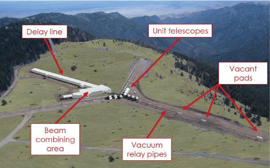
for the Interferometer. The ten unit telescopes are configured in a Y-shaped array. The telescopes can be lifted and
relocated to vacant pads to optimise the interferometer for viewing features of different sizes
Figure 2 depicts the simulated performance of the MROI when imaging the surface of a distant red giant star. Figure 3 demonstrates an application closer to Earth in which the MROI will image geostationary satellites to enhance space situational awareness.
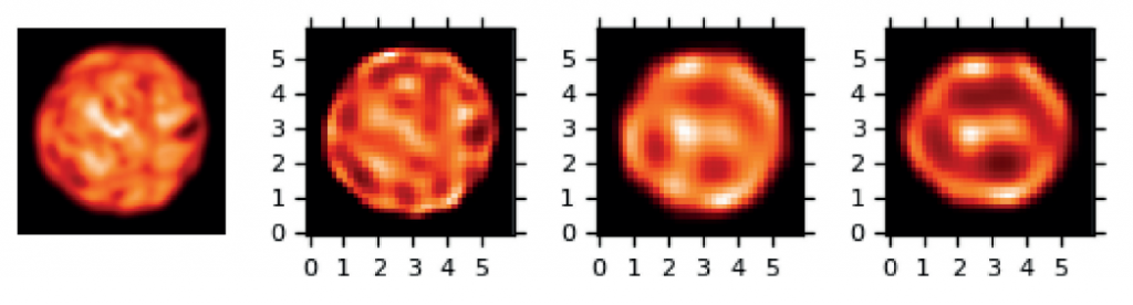
distance of 11,000 light years. From left to right: 1. “Truth” (Chiavassa, A., Plez, B., Josselin, E., Freytag, B., “Radiative
hydrodynamics simulations of red supergiant stars. I. interpretation of interferometric observations”, Astronomy
and Astrophysics, 506, p1351 (2009)). 2. Reconstructed image with 10 telescopes, 3. With 7 telescopes, 4. With 4
telescopes. A more faithful image results from using greater numbers of telescopes, particularly with regard to the
locations of hotspots.
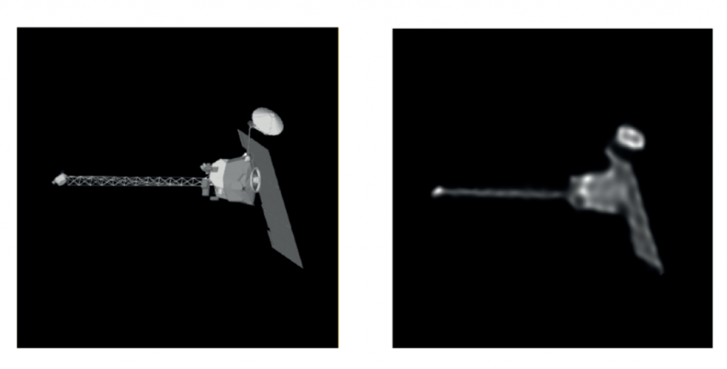
simulated performance of the MROI when using 10 telescopes. The satellite is 17 m in length and 35000 km
away, so this situation is comparable to imaging a £1 coin from a distance of 50 km.
Interferometric measurements are incredibly sensitive to the alignment of the pairs of beams being combined. For example, an angular drift of 10 µrad during observations is intolerable. An Automated Alignment System (AAS) has been developed for the MROI that will, prior to nightly observing, align the ten beamlines with minimal human interaction. As the night progresses, the AAS will correct thermally-induced drifts.
At the heart of the AAS is an alignment detector called BEASST that is placed in the beam combining laboratory. Similarly to a Shack-Hartmann sensor, it samples the beam pupil with a microlens array. A Raptor Owl 640-II is placed at the focal plane of the microlenses. Figure 4 displays typical image readouts from BEASST, which consist of an array of focal spots. Most beam alignment detectors can only measure either the angle or position of a collimated beam. In contrast, BEASST measures both parameters simultaneously. The beam angle is calculated from displacements of the focal spots while the beam position is determined from the centroid of the pupil intensity distribution.
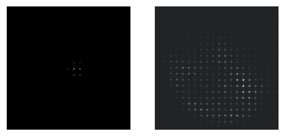
light (right). The low gain mode of the Owl 640-II was used to maximise dynamic range when the reference
source was used, while the high gain mode was used to maximise sensitivity when the stellar beam was used.
The stellar beam profile is randomly speckled due to its passage through the turbulent atmosphere.
The compact housing of the Raptor Owl 640-II allows ten BEASSTs to be placed in close proximity without
blocking the multitude of light beams that propagate in the laboratory. Its low power consumption is also helpful, since dissipated heat induces air turbulence that disturbs alignment on fast timescales. Furthermore, its optional compatibility with the GigE interface has been critical in our application in which the controlling computer is located far from the cameras. Multiplexing the ten cameras will be trivial since their images can be streamed to any PC connected to the network.
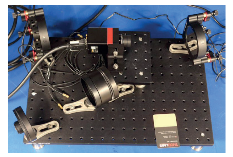
A prototype of BEASST was deployed at the Observatory. The Owl 640-II was essential for a number of commissioning measurements. For example, it was used to diagnose the collimation of an invisible reference light beam (see Figure 5). In another application it streamed images at 120 Hz to identify the cause of high frequency alignment disturbances (see Figure 6). Finally, it was used to detect stellar light in the beam combining laboratory for the first time (see Figure 7), which was an important milestone for the MROI.
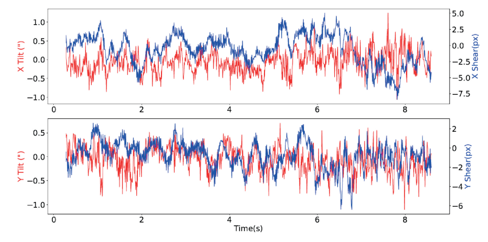
the Raptor Owl 640-II. Plotted against elapsed time are the extracted beam alignment parameters: the angle
(tilt), coloured red, and the position (shear), coloured blue. The top and bottom plots correspond to the
horizontal (X) and vertical (Y) directions, respectively. We identified fluctuations at frequencies up to 60 Hz.
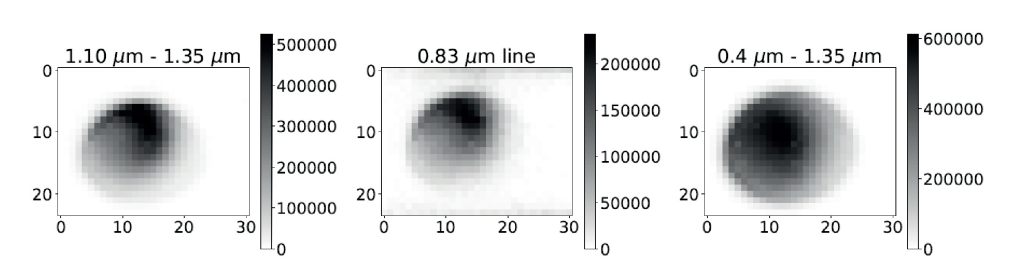
range of the Raptor Owl 640-II between 600 nm and 1700 nm allowed observations at various bandpasses
that assisted the interpretation of the results. Note that these images are reduced from the style of images
shown in Figure 4 (i.e. they are not direct images of the star).
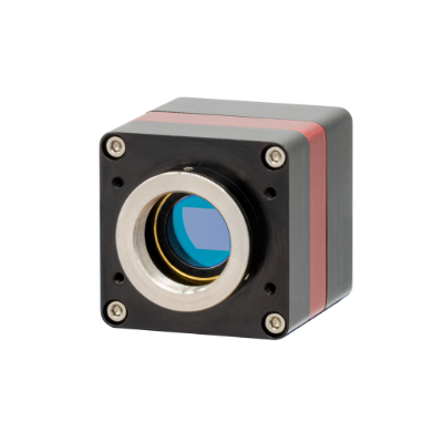
Discover the Raptor Photonics OWL 640 II VIS SWIR Camera
High Resolution, Low Noise, Digital VIS-SWIR InGaAs Camera
The Magdalena Ridge Observatory Interferometer (MROI) project’s mission is to develop a ten-element imaging interferometer to operate at wavelengths between 0.6 and 2.4 microns with baselines from 7.8 to 340 meters. The technical and scientific goals are to produce model-independent images of faint and complex astronomical targets at resolutions over 100 times that of the Hubble Space Telescope. The goal of the MROI is threefold, to support programs in:
- Astronomy
- Space situational awareness
- Education & outreach
The astronomical science program includes the following three areas:
- Star and planet formation
- Stellar accretion and mass loss
- Active galactic nuclei


Do you have any questions regarding the Raptor Owl 640 II or Interferometry?
Get in touch with our Technical Sales Manager, Dr. Luke Nicholls, by email or call (01372) 378822
This material is based on research sponsored by Air Force Research Laboratory (AFRL) under agreement number FA9453-15-2-0086. The U.S. Government is authorized to reproduce and distribute reprints for Governmental purposes notwithstanding any copyright notation thereon. The views and conclusions contained herein are those of the authors and should not be interpreted as necessarily representing the official policies or endorsements, either expressed or implied, of Air Force Research Laboratory (AFRL) and or the U.S. Government.


