Ellipsometers
Measure your Film Thickness and Optical Constants by Ellipsometry
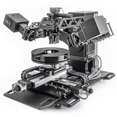
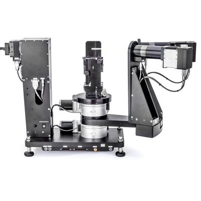
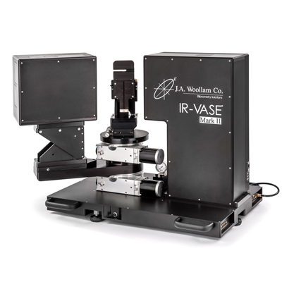
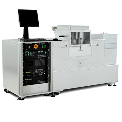
We offer a wide range of spectroscopic ellipsometers, optimised for your particular application.
This tutorial provided by the J. A. Woollam Co. is an introduction to ellipsometry for anyone interested in learning more about ellipsometry and its applications. This tutorial is written with the novice in mind, but experienced ellipsometry users will also benefit from the information presented in this discussion.
Ellipsometry measures a change in polarisation as light reflects or transmits from a material structure. The polarisation change is represented as an amplitude ratio, Ψ, and the phase difference, Δ. The measured response depends on optical properties and thickness of individual materials. Thus, ellipsometry is primarily used to determine film thickness and optical constants. However, it is also applied to characterise composition, crystallinity, roughness, doping concentration, and other material properties associated with a change in optical response.
Since the 1960s, as ellipsometry developed to provide the sensitivity necessary to measure nanometer-scale layers used in microelectronics, interest in ellipsometry has grown steadily. Today, the range of its applications has spread to the basic research in physical sciences, semiconductor and data storage solutions, flat panel display, communication, biosensor, and optical coating industries. This widespread use is explained by increased dependence on thin films in many areas and the flexibility of ellipsometry to measure most material types: dielectrics, semiconductors, metals, superconductors, organics, biological coatings, and composites of materials.
This tutorial provides a fundamental description of ellipsometry measurements along with the typical data analysis procedures. The primary applications of ellipsometry are also surveyed.
Light can be described as an electromagnetic wave traveling through space. For purposes of ellipsometry, it is adequate to discuss the waves’s electric field behavior in space and time, also known as polarisation. The electric field of a wave is always orthogonal to the propagation direction. Therefore, a wave traveling along the z-direction can be described by its x- and y- components. When the light has completely random orientation and phase, it is considered unpolarised. For ellipsometry, however, we are interested in the kind of electric field that follows a specific path and traces out a distinct shape at any point. This is known as polarised light. When two orthogonal light waves are in-phase, the resulting light will be linearly polarised. The relative amplitudes determine the resulting orientation. If the orthogonal waves are 90° out-of-phase and equal in amplitude, the resultant light is circularly polarised. The most common polarisation is “elliptical”, one that combines orthogonal waves of arbitrary amplitude and phase. This is where ellipsometry gets its name.
Two values are used to describe the optical properties which determine how light interacts with a material. They are generally represented as a complex number. The complex refractive index (ñ) consists of the index (n) and extinction coefficient (k):
ñ = n + ik
Alternatively, the optical properties can be represented as the complex dielectric function:
ɛ̃ = ε1 + iε2
with the following relation between conventions:
ɛ̃ = ñ2
The index describes the phase velocity of light as it travels in a material compared to the speed of light in vacuum, c:
v = c / n
Light slows as it enters a material with higher index. Because the frequency of light waves remains constant, the wavelength will shorten. The extinction coefficient describes the loss of wave energy to the material. It is related to the absorption coefficient, α, as:
α = 4πk / λ
Light loses intensity in an absorbing material according to Beer’s Law:
I (x) = I0e-iαx
Thus, the extinction coefficient relates how quickly light vanishes in a material. These concepts are demonstrated in Figure 2 where a light wave travels through two different materials of varying properties before returning to the ambient.
Wave travels from air into absorbing Film 1 and then transparent Film 2. The phase velocity and wavelength change in each material depending on index of refraction (Film 1: n=4, Film 2: n=2).
The optical constants for TiO2from the ultraviolet (UV) to the infrared (IR), as shown in Figure 3. The optical constants are determined by wavelength with absorption (k>0) occurring in both UV and IR due to different mechanisms that take energy from the light wave. IR absorption is commonly caused by molecular vibration, phonon vibration, or free-carriers. UV absorption is generally due to electronic transitions, where light provides energy to excite an electron to an elevated state. A closer look at the optical constants in the figure below shows that real and imaginary optical constants are not independent. Their shapes are mathematically coupled through Kramers-Kronig consistency.
Complex dielectric function for TiO2film covering wavelengths from the infrared (small eV) to the ultraviolet (high eV).
Maxwell’s equations must remain satisfied when light interacts with a material, which leads to boundary conditions at the interface. Incident light will reflect and refract at the interface, as shown in the figure below. The angle between the incident ray and sample normal (θi) will be equal to the reflected angle, (θr). Light entering the material is refracted at an angle θt given by:
ni sin θi = nt sin θt
Light reflects and refracts according to Snell’s law.
The same occurs at each interface where a portion of light reflects and the remainder transmits at the refracted angle. The boundary conditions provide different solutions for electric fields parallel and perpendicular to the sample surface. Therefore, light can be separated into orthogonal components with relation to the plane of incidence. Electric fields parallel and perpendicular to the plane of incidence are considered p- and s- polarised, respectively. These two components are independent and can be calculated separately. Fresnel described the amount of light reflected and transmitted at an interface between materials:
rp ≡ Erp / Eip = (nt cos θi– ni cos θt) / (nt cos θi+ ni cos θt)
tp ≡ Etp / Eip = (2ni cos θi ) / (nt cos θi+ ni cos θt)
rs ≡ Ers / Eis = (ni cos θi– nt cos θt) / (ni cos θi+ nt cos θt)
ts ≡ Ets / Eis = (2ni cos θi ) / (ni cos θi+ nt cos θt)
Thin film and multilayer structures involve multiple interfaces, with Fresnel reflection and transmission coefficients applicable at each. It is important to track the relative phase of each light component to determine correctly the overall reflected or transmitted beam. For this purpose, we define the film phase thickness as:
β = 2π(d1 / λ)n1 cos θi
The superposition of multiple light waves introduces interference that depends on the relative phase of each light wave. The figure below illustrates the combination of light waves in the reflected beam and their corresponding Fresnel calculations.
Light reflects and refracts at each interface, which leads to multiple beams in a thin film. Interference between beams depends on relative phase and amplitude of the electric fields. Fresnel refection and transmission coefficients can be used to calculate the response from each contributing beam.
Ellipsometry is primarily interested in how p- and s- components change upon reflection or transmission in relation to each other. In this manner, the reference beam is part of the experiment. A known polarisation is reflected or transmitted from the sample and the output polarisation is measured. The change in polarisation is the ellipsometry measurement, commonly written as:
ρ = tan (Ψ) eiΔ
A sample ellipsometry measurement is shown in Figure 6. The incident light is linear with both p- and s- components. The reflected light has undergone amplitude and phase changes for both p- and s- polarised light, and ellipsometry measures their changes.
Spectroscopic Ellipsometry Tutorial Ellipsometry Measurements model
The primary tools for collecting ellipsometry data all include the following: light source, polarisation generator, sample, polarisation analyzer, and detector. The polarisation generator and analyzer are constructed of optical components that manipulate the polarisation: polarisers, compensators, and phase modulators. Common ellipsometer configurations include rotating analyzer (RAE), rotating polariser (RPE), rotating compensator (RCE), and phase modulation (PME).
The RAE configuration is shown in the figure above. A light source produces unpolarised light which is then sent through a polariser. The polariser allows light of a preferred electric field orientation to pass. The polariser axis is oriented between the p- and s- planes, such that both arrive at the sample surface. The linearly polarised light reflects from the sample surface, becomes elliptically polarised, and travels through a continuously rotating polariser (referred to as the analyzer). The amount of light allowed to pass will depend on the polariser orientation relative to the electric field “ellipse” coming from the sample. The detector converts light to electronic signal to determine the reflected polarisation. This information is compared to the known input polarisation to determine the polarisation change caused by the sample reflection. This is the ellipsometry measurement of Psi and Delta.
Ellipsometry measures changes in light polarization to determine the sample material’s properties of interest, such as film thickness and optical constants. In the case of a bulk material, the equations derived for a single reflection can be directly inverted to provide the “pseudo” optical constants from the ellipsometry measurement, r:
⟨ɛ̃⟩= sin2 θi [1 + tan2 θi ((1 – ρ) / (1 + ρ))2]
This equation assumes there are no surface layers of any type. However, in any bulk material, there is typically a surface oxide or roughness, and the direct inversion would include these as part of the bulk optical constants. The more common procedure used to deduce material properties from ellipsometry measurements follows the flow chart below. Regression analysis is required because an exact equation cannot be written. Often the answer is over-determined with hundreds of experimental data points for a few unknowns. Regression analysis allows all of the measured data to be included when determining the solution.
Flow chart for ellipsometry data analysis.
Data analysis proceeds as follows: After a sample is measured, a model is constructed to describe the sample. The model is used to calculate the predicted response from Fresnel’s equations which describe each material with thickness and optical constants. If these values are not known, an estimate is given for the purpose of the preliminary calculation. The calculated values are compared to experimental data. Any unknown material properties can then be varied to improve the match between experiment and calculation. The number of unknown properties should not exceed the amount of information contained in the experimental data. For example, a single-wavelength ellipsometer produces two data points (Ψ,Δ) which allows a maximum of two material properties to be determined. Finding the best match between the model and the experiment is typically achieved through regression. An estimator, like the Mean Squared Error (MSE), is used to quantify the difference between curves. The unknown parameters are allowed to vary until the minimum MSE is reached.
The best answer corresponds to the lowest MSE. For example, the figure below shows the MSE curve versus film thickness for a transparent film on silicon. There are multiple “local” minima, but the lowest MSE value occurs at a thickness = 749 nm. This corresponds to the correct film thickness. It is possible that the regression algorithm will mistakenly fall into a “local” minima depending on the starting thickness and the MSE structural conditions. Comparing the results by eye for the lowest MSE and a local minima allows you to distinguish the true global minimum easily.
Figure (bottom) MSE curve versus thickness shows the ‘global’ minimum. ‘Local’ minima may be found by the regression algorithm, but do not give the final result. Figure (top-right) The experimental data and corresponding curves generated for the model at the ‘global’ minimum. Figure (top-left) Similar curve at the ‘local’ minimum near 0.45 microns thickness is easily distinguishable as an incorrect result.
The film thickness is determined by interference between light reflecting from the surface and light traveling through the film. Depending on the relative phase of the rejoining light to the surface reflection, interference can be defined as constructive or destructive. The interference involves both amplitude and phase information. The phase information from Δ is very sensitive to films down to sub-monolayer thickness. The figure below compares reflected intensity and ellipsometry for the same series of thin SiO2layers on Si. There are large variations in Δ, while the reflectance for each film is nearly the same.
(left) Reflected intensity and (right) ellipsometric delta for two thin oxides on silicon show the high sensitivity of Delta to nanometer scale films not observable with the intensity measurement.
Ellipsometry is typically used for films whose thickness ranges from sub-nanometers to a few microns. As films become thicker than several tens of microns, interference oscillations become increasingly difficult to resolve, except with longer infrared wavelengths. Other characterisation techniques are preferred in this case.
Thickness measurements also require that a portion of the light travel through the entire film and return to the surface. If the material absorbs light, thickness measurements by optical instruments will be limited to thin, semi-opaque layers. This limitation can be circumvented by targeting measurments to a spectral region with lower absorption. For example, an organic film may strongly absorb UV and IR light, but remain transparent at mid-visible wavelengths. For metals, which strongly absorb at all wavelengths, the maximum layer for thickness determination is typically about 100 nm.
Thickness measurements are not independent of the optical constants. The film thickness affects the path length of light traveling through the film, but the index determines the light waves’ velocity and refracted angle. Thus, both contribute to the delay between surface reflection and light traveling through the film. Both n and k must be known or determined along with the thickness to get the correct results from an optical measurement.
The optical constants for a material will vary for different wavelengths and must be described at all wavelengths probed with the ellipsometer. A table of optical constants can be used to predict the material’s response at each wavelength. However, it is not very convenient to adjust unknown optical constants on a wavelength-by-wavelength basis. It is more advantageous to use all wavelengths simultaneously. A dispersion relationship often solves this problem, by describing the optical constant shape versus wavelength. The adjustable parameters of the dispersion relationship allow the overall optical constant shape to match the experimental results. Compared to fitting individual n, k values at every wavelength, this greatly reduces the number of unknown “free” parameters.
For transparent materials, the index is often described using the Cauchy or Sellmeier relationship. The Cauchy relationship is typically given as:
n(λ) = A + B / λ2 + C / λ4
where the three terms are adjusted to match the refractive index for the material. The Cauchy is not constrained by KK consistency and can produce unphysical dispersion. The Sellmeier relationship enforces Kramers-Kronig (KK) consistency, which ensures that the optical dispersion retains a realistic shape. The Sellmeier relationship can be written as:
ε1 = Aλ2λ02 / (λ2 – λ02)
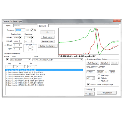
Absorbing materials will often have a transparent wavelength region that can be modeled with the Cauchy or Sellmeier. However, the absorbing region must account for both real and imaginary optical constants. Many dispersion relationships use oscillator theory to describe absorption for various materials. These include the Lorentz, Harmonic, and Gaussian oscillators. They all share similar attributes, where the absorption features are described with an Amplitude, Broadening, and Center Energy (related to frequency of light). Kramers-Kronig consistency is used to calculate the shape of the real component after the imaginary behavior is described by the oscillator. An offset to the real component is added to account for extra absorption outside the measured spectral region. The Lorentz oscillator can be written as:
ɛ̃ = ε1 off set + AEC / (EC2 – E2 – iBE)
where the parameters for Amplitude (A), Broadening (B), Center Energy (Ec), and offset (ε1 off set) are also shown in the figure belowfor a typical Lorentz oscillator. The energy, E, is related to the frequency of a wave, n:
E = hν ≅1240 / λnm
where h is Planck’s constant and the wavelength, l, is given in nanometers. More advanced dispersion models, like the Tauc-Lorentz and Cody-Lorentz, will include terms to describe the bandgap energy.
Single wavelength ellipsometry or spectroscopic ellipsometry, is a method to determine layer thickness and optical constants of thin films or substrates. An ellipsometer, either single wavelength or a spectroscopic, measures the polarisation change at reflection (or transmission in case of anisotropic sample). J. A. Woollam is the worldwide leader and the company has been perfecting spectroscopic ellipsometry for over 30 years.
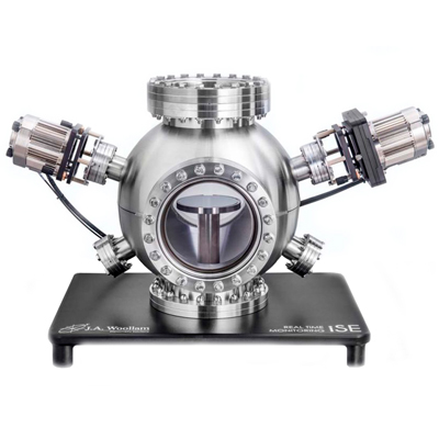
The flexible ellipsometer VASE, based on a scanning monochromator, is ideal for all kinds of R&D applications, covering the widest spectral range in the market from 140 to 3200 nm, or in combination with IR-VASE up to 30 µm. Alternatively, Woollam’s fast CCD based, rotating compensator spectroscopic ellipsometers M-2000 and RC2 are available for ex-situ as well as in-situ applications. Woollam have also introduced the iSE which is designed specifically for in-situ monitoring of thickness and optical properties. Recently introduced, the theta-SE is a push-button spectroscopic ellipsometer for characterising thin film uniformity.
