


- Features
- Models
- Downloads
- Specification
- Related Products
- Contact
- Back To Spectroscopy
- Back To Optics
- Back To Hyperspectral
- Back To Cameras
- Back To X-Ray
- Back To Light Measurement
- Back To PPMS
- Back To Electron Microscopy
- Back To Magnetometers
- Back To Ellipsometers
- Back To Cryogenics
- Back To Lake Shore
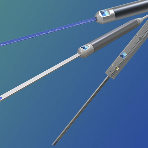
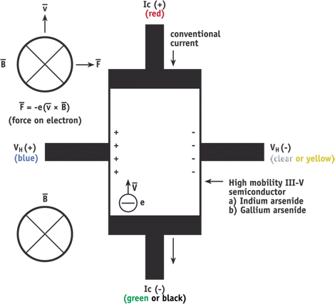
InAs and GaAs Hall Sensors
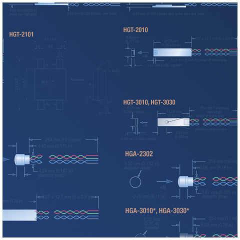
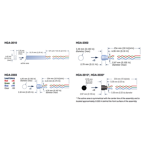
Transverse devices are generally thin and rectangular in shape. They are applied successfully in magnetic circuit gaps, surface measurements, and general open field measurements.
Axial sensors are mostly cylindrical in shape. Their applications include ring magnet centre bore measurements, solenoids, surface field detection, and general field sensing. See the individual Hall sensor illustrations for physical dimensions.
InAs and GaAs Hall Sensor Features
- Multiple packages available
- Options for high stability or sensitivity
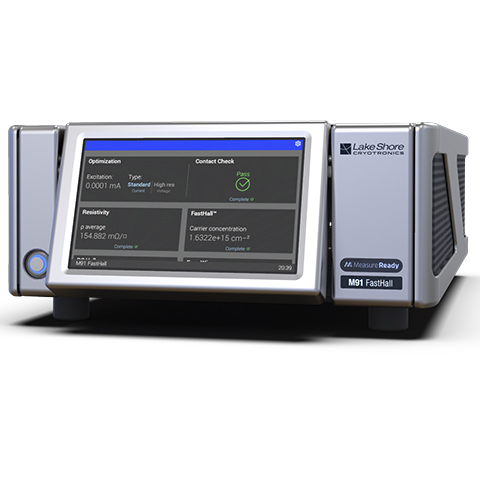
- Compatible with Lake Shore 400 Series gaussmeters


Model Guides
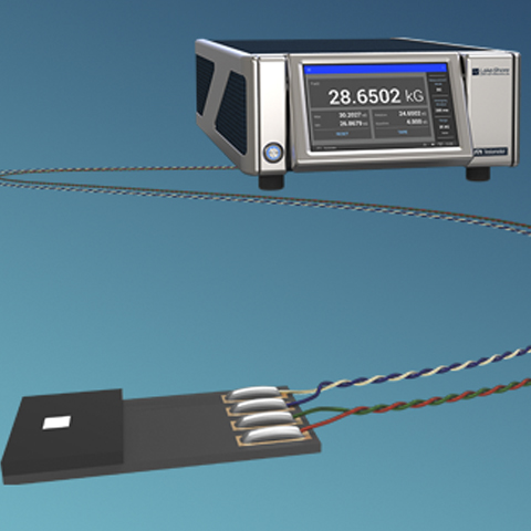
A Hall sensor is a 4-lead device. The control current (IC) leads are normally attached to a current source such as the Lake Shore Model 121. The Model 121 provides several fixed current values compatible with various Hall sensors.
Caution: Do not exceed the maximum continuous control current given in the specifications.
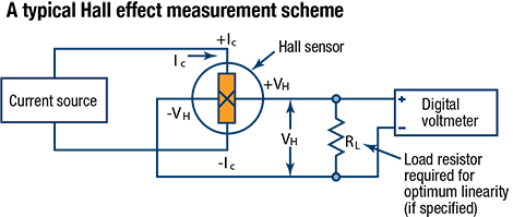
The Hall voltage leads may be connected directly to a readout instrument, such as a high impedance voltmeter, or can be attached to electronic circuitry for amplification or conditioning. Device signal levels will be in the range of microvolts to hundreds of millivolts.
The Hall sensor input is not isolated from its output. In fact, impedance levels on the order of the input resistance are all that generally exist between the two ports. To prevent erroneous current paths, which can cause large error voltages, the current supply must be isolated from the output display or the down stream electronics.
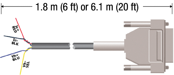
Lake Shore provides cable assemblies containing the necessary electronic memory (EEPROM) to interface a InAs Hall sensor to a gaussmeter. This allows users to assemble a Hall sensor into a difficult to access area prior to gaussmeter attachment. The figure below shows the general cable configuration. While convenient, this method provides less than optimum performance. Because of the intricacies involved with proper calibration, the user is responsible for the measurement accuracy. A probe fully calibrated by Lake Shore is always suggested.
Certain Hall sensor sensitivity constraints are applicable:
—Sensitivities between 5.5 and 10.5 mV/kG at 100 mA control current.
—Sensitivities between 0.55 and 1.05 mV/kG at 100 mA control current.
For Model 475, 455, and 425 gaussmeters
For legacy Model 460, 450, and 421 gaussmeters
Connection of discrete Hall sensors to these instruments is no longer supported.
Downloads

Supplier Info
InAs and GaAs Hall Sensor Specifications
Specifications