- Features
- Models
- Specifications
- Downloads
- Applications
- Related Products
- Contact
- Back To Spectroscopy
- Back To Optics
- Back To Hyperspectral
- Back To Cameras
- Back To X-Ray
- Back To Light Measurement
- Back To Characterisation
- Back To Electron Microscopy
- Back To Magnetometry
- Back To Ellipsometers
- Back To Cryogenics
- Back To Lake Shore
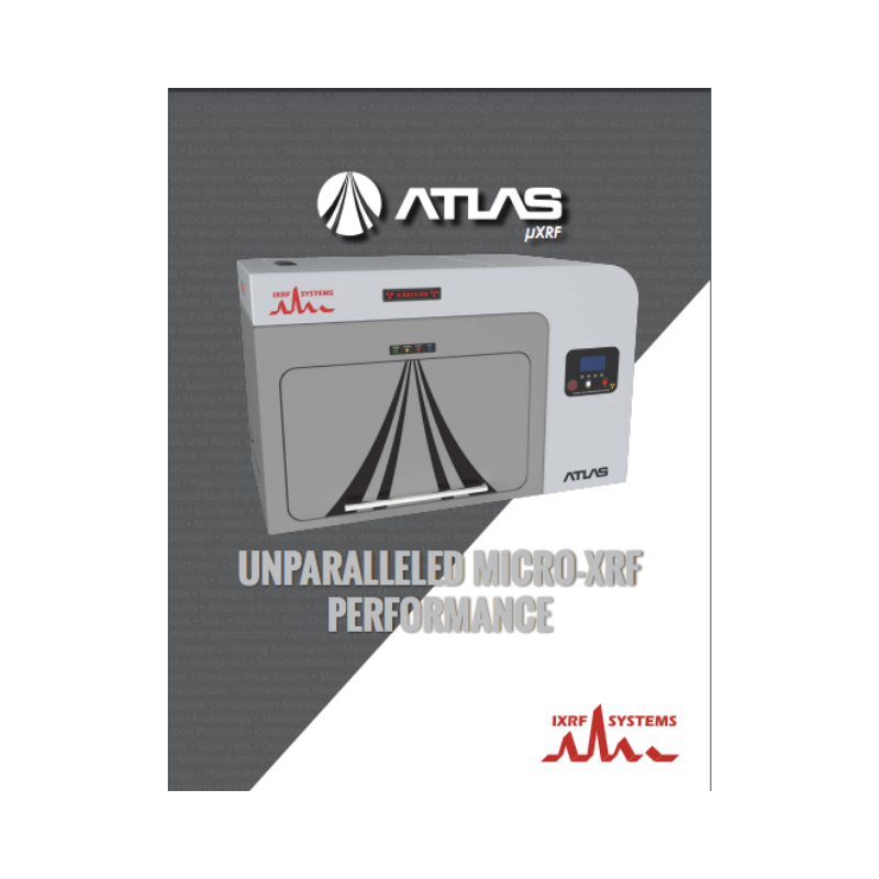
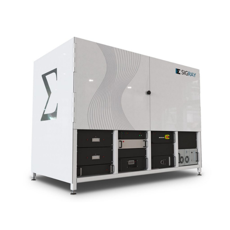
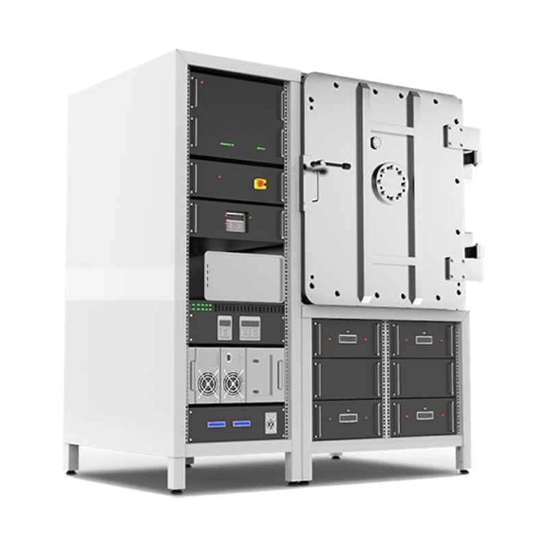
IXRF ATLAS X : micro XRF Spectrometer
Micro X-ray Fluorescence Hyperspectral Imager for Elemental Analysis
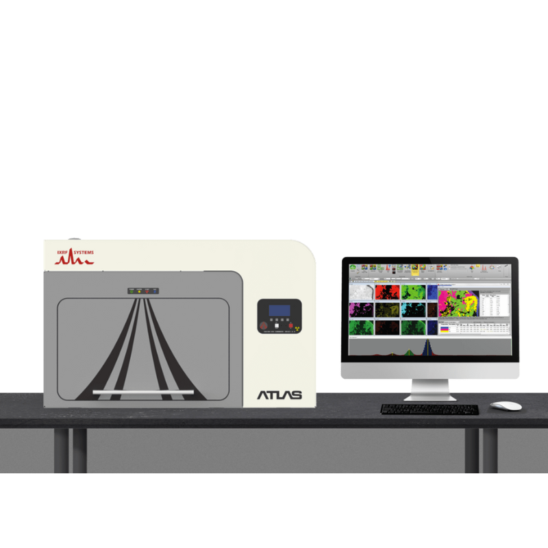
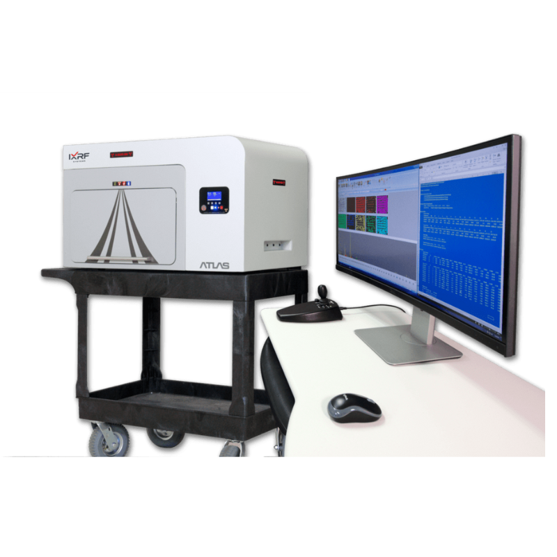
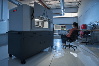
IXRF Systems’ ATLAS X mainframe micro-XRF spectrometer is the latest general purpose micro/small spot energy dispersive X-ray fluorescence (μXRF) spectrometer for the measurement and imaging/mapping of elements from sodium (Na) through uranium (U).
Designed to image and analyse a wide variety of sample types, ATLAS leads the industry in virtually every major specification category from the most powerful software and the largest detector active area, to our superior perpendicular geometry and tiny 5 μm diameter micro XRF spot.
FEATURES
- Largest sample chamber in the industry
- Spot size down to 5 microns with anti-halo optic
- SDD detectors w/ active area up to 150 mm2
- Edge-to-edge mapping of 300 mm wafers
- 50 kV / 50 W polycapillary optic micro X-ray source
- Multi-point/multi-area automation & mapping
- Air, vacuum, helium for solids, liquids, and powders
- Iridium Ultra software running on Windows™ 10 OS
The 5 micron advantage
ATLAS X micro-XRF mapping spectrometer is the mainframe tool of choice for sample characterisation using small-spot micro X-ray fluorescence (micro-EDXRF) spectrometry for information on composition (phase) and elemental distribution. With the smallest X-ray spot in the industry at 5 microns, ATLAS X is optimised for analysis speed without compromising accuracy. The instrument can measure a wide range of sample types, whether small or large, even or irregularly shaped. Equipped with a large high-speed stage, it supports 2D analysis of virtually any kind of sample: solids, liquids, powders, thin-films and particles. Its extra large vacuum chamber delivers superior light element (low-Z) sensitivity.
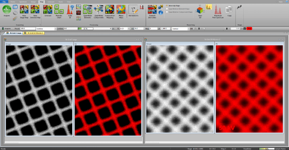
When it comes to micro-X-ray microscopic imaging (mapping), smaller is always better. Pictured here is a TEM grid. The image on the left was captured using the ATLAS X’s 5 micron X-ray spot. The inferior image on the right was taken with a 10 micron X-ray spot.
Biggest chamber
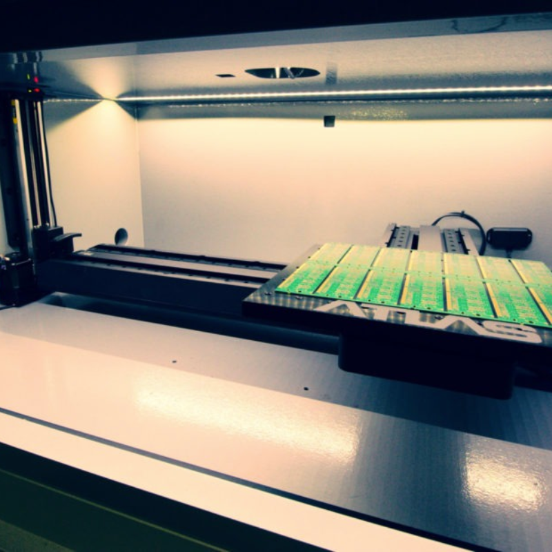
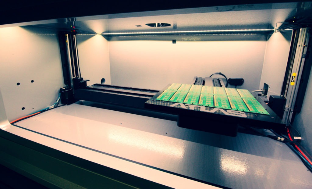
ATLAS X micro-XRF imaging spectrometer features the industry’s most voluminous sample chamber, allowing for automation of more samples, larger area mapping capabilities, and wider variability of sample types that can be analysed. Sample chamber size: 940 x 660 x 355 mm (37 x 26 x 14 inches).
Superior geometry
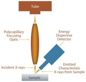
- Perpendicular ATLAS X geometry allows for circular excitation down to 5 microns for highest spatial resolution.
- Competitor’s inferior angled geometry only allows smallest spot to be 25 microns due to the ellipse.
Unmatched speed
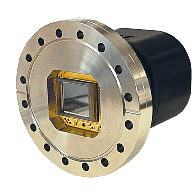
- Mix and match up to 4 Silicon Drift Detectors (SDD)
- For the largest possible solid angle collection efficiency
- Up to 600 mm2 active area
- Available resolutions: ≤130-145 eV resolution
- Highest count rate with the smallest spot for fast high-res images

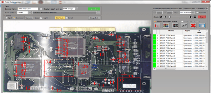
Overview automation
Overview video camera mode:
- Automated spectral spot analysis
- Automated X-Ray mapping
- Automated linescans
- Large chamber view for large samples
Sample types and conditions
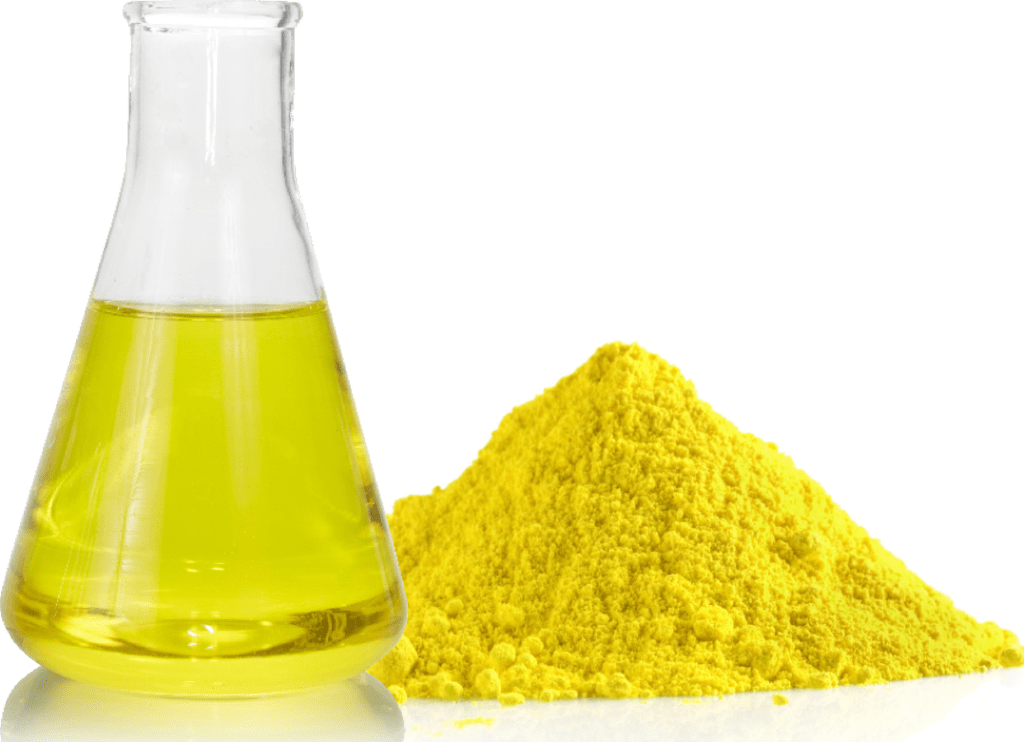
- Air, vacuum or helium atmosphere
- Vacuum ready in under one minute
- Allows, solids, liquids, powders, particles and multi-layer thin films
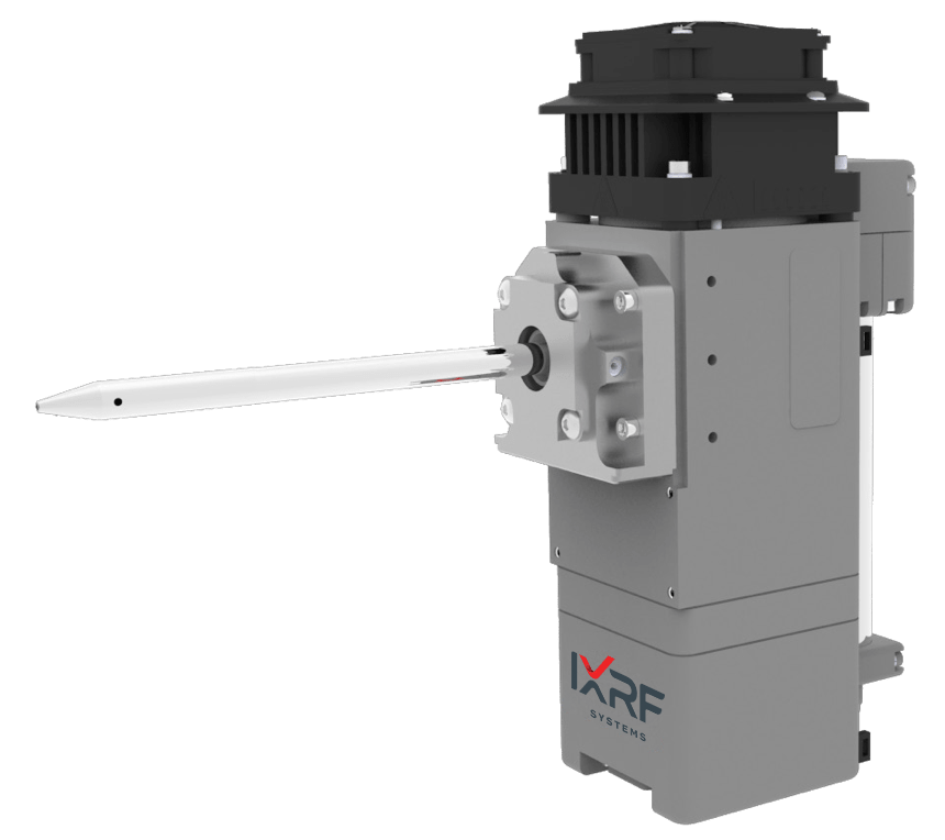
Micro X-ray Excitation
- 50 kV / 50 W / 1 mA Rh target (others available) X-ray tube
- Polycapillary focusing optic
- Filter wheel with up to 7 filters (plus open position) before the focusing optic
- Available primary X-ray spot sizes: 5 , 10, 20 or 40 μm
- Optional second X-ray tube, with a choice of anodes, is available with spot sizes of 200, 500 or 1000 μm
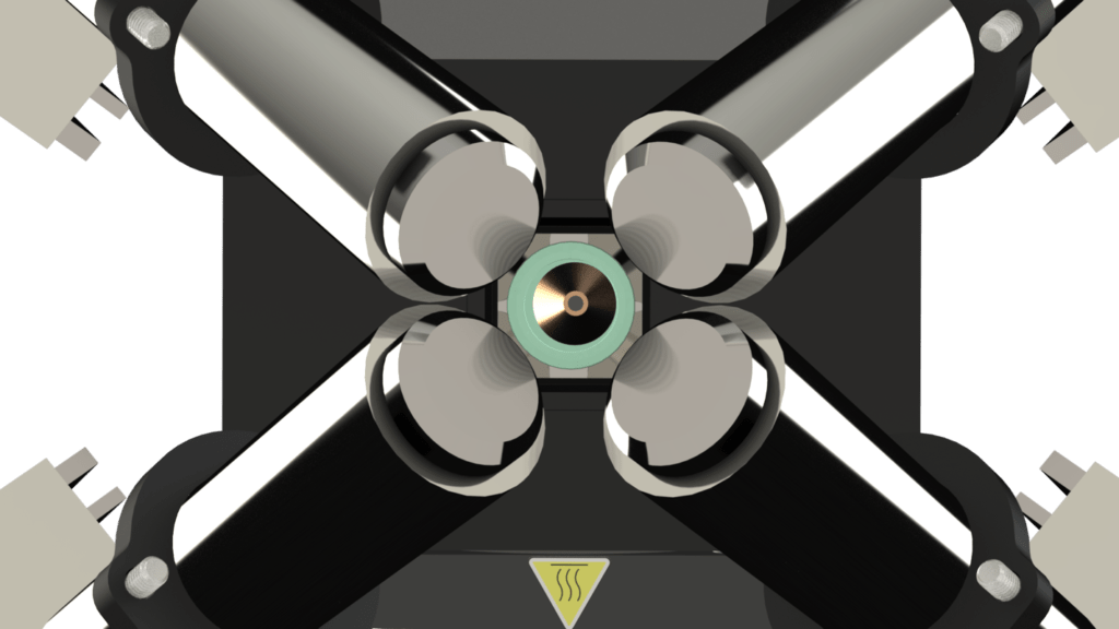
X-ray
Detection
- Mix and match up to 4 Silicon Drift Detectors (SDD)
- For increased precision and/or reduced acquisition times
- 50 mm2 to 150 mm2 active area
- Highest resolution to highest counting rate
- Available resolutions: ≤130-145 eV resolution
- Peltier cooling
Largest precision stages
- Motorised XY, Z optional
- Mapping travel: 400(X) x 300(Y) mm
- Speeds up to 300mm/s
- Map acquisitions at ≤ 1ms/pixel
- Accuracy < 1µm
- Custom adapters available
Chamber and geometry
- Chamber size: 950 x 650 x 365 mm (37 x 26 x 14 inches)
- Top-down perpendicular geometry from tube to sample
- Mapping area: 400 x 300 mm under automatic control
- Sample view: 3 sample positioning and analysis cameras
- Samples may be positioned manually with the door open
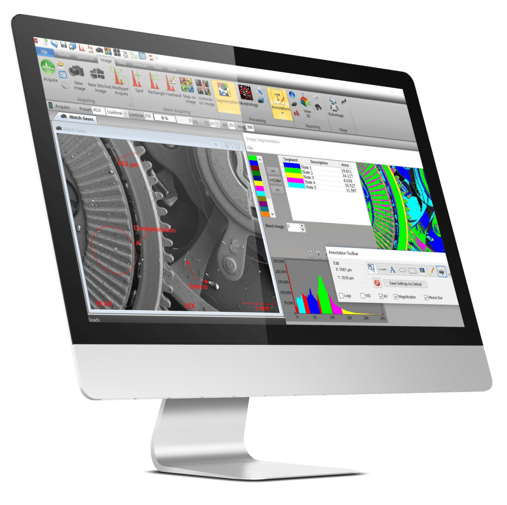
Iridium Ultra™ for Windows® 10
- Energy dispersive X-ray fluorescence (microEDXRF) spectroscopic software
- Fundamental Parameters (FP) for solids, liquids, powders and particles
- Thin film FP for up to 8 layers including an infinite base or substrate
- Automatic treatment for sum/escape peaks and full deconvolution
- Up to 8 acquisition conditions per analysis
- Hyperspectral EDXRF mapping and imaging, up to 4096 x 4096 pixels
- Every pixel is a full EDXRF spectrum
- Principal component analysis (PCA) for phase mapping
- Materials classification database
Acquisition and quantitation
- One-click acquisition and automatic peak identification
- Customisable identification, labeling, processing, and quantification
- Scrolling periodic chart
- Drag and drop overlay
- Automatic overlap correction, sum/escape peak removal, background correction, and linear/non-linear deconvolution
- Fundamental Parameters (FP) and Quantitative Match
- Material classification database
Imaging and analysis
- Multi-Point automated analysis directly from image
- Morphological processing for rapid feature size measurements
- Image stitching and montage
- Segmentation and feature segregation
- Particle analysis package
- Including border removal, sorting and exclusion
- Classification by composition
Mapping and linescans
- Simultaneous acquisition of 35 elements
- Stored spectral data for every pixel
- Live spectrum display during acquisition
- Single or multiple map acquisition from image
- Overview or spot camera
- Map stitching and montage
- Extract spectra from map: point, area, freehand
- Create linescan from map
- Mouse-over view intensities and concentrations
- Phase Analysis
- Multi-compositional map display
- Of element and compound ranges
- Overlay linescans on image
Specialty and automation
- Multilayer thin film and coatings analysis up to 8 layers
- Serpentine continuous mapping (dual directional mapping)
- ASTM E2926-13 Glass Analysis
- Track, store, and recall all stage locations and images
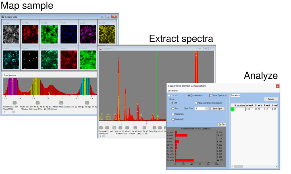
Imaging / mapping flow
- Create multiple X-ray maps on any region on the sample
- Define map parameters directly from video image
- Combine pixels to create analysis regions
- Regions are summed to create a composite spectrum
- Automatically identify elemental peaks
- Apply analytical quantification method
- Analytical results are displayed as a graphic
SPECIFICATIONS
- Elemental range: Sodium (Na) through uranium (U)
- Sample types: Solids, liquids, particles, powders and thin films
- Sample chamber size:940 x 660 x 355 mm (37 x 26 x 14 inches)
- Analysis atmosphere: Air, vacuum or He(g) purge
- Primary X-ray source: 50 W max power, 50 kV @ 1 mA
- Optional secondary X-ray source: 4-12 W max power, 40-60 kV @ 0.4-1 mA
- X-ray source optics: Polycapillary or aperture collimation
- X-ray source anode: Rhodium (others optionally available)
- X-ray source spot size (primary): 5 μm standard (optional: 10, 20 or 40 μm)
- X-ray source filters: Up to 7 plus an open position
- Primary X-ray source geometry: Top-down beam (perpendicular to sample stage)
- Detector(s): 1 standard, optionally up to a maximum of 4
- Detector types: Silicon drift detector (SDD) standard (PIN-diode is optionally available)
- Detector active area: 50 to 150 mm2, up to 600 mm2 w/ 4 detectors
- Sample stage type: Motorised X,Y and Z (optional)
- Sample stage travel:600(W) x 300(D) x 210(H) mm
- Mapping travel:300(X) x 400(Y) mm
- Mapping scan speed: 1-3 ms/pixel
- Stage XY speed: Up to 300 mm/s
- Sample view: 3 cameras for sample positioning and analysis
- Operating system: SFF PC w/ Microsoft® Windows™ 10 OS
- Analysis and control software: Iridium Ultra: provides complete control of parameters, filters, cameras, optical microscopes, sample illumination and positioning, and measurement media
- Quality and safety: CE marked, RoHS, radiation < 0.5 μSv/h
- Dimensions:1690(L) x 787(W) x 1630(H) mm (67 x 31 x 64 inches)
- Power: 100-240 V, 1 phase, 50/60 Hz


